Installation
EB62 MANUAL TRANSAXLE: MANUAL TRANSAXLE ASSEMBLY: INSTALLATION
NOTICE:
When the transaxle is removed, be sure to use a new clutch release with bearing cylinder and new installation bolts. Removal of the transaxle allows the compressed clutch release with bearing cylinder to return to its original position, and dust from the moving section could damage the seal of the clutch release with bearing cylinder, possibly causing clutch fluid leaks.
1. INSTALL SPEEDOMETER DRIVEN HOLE COVER SUB-ASSEMBLY
(a) Coat a new O-ring with gear oil.
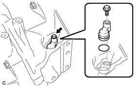
(b) Install the O-ring onto the speedometer driven hole cover.
(c) Install the speedometer driven hole cover sub-assembly onto the transaxle case with the bolt.
Torque : 5.5 Nm (56 kgf-cm, 49 in-lbf)
2. INSTALL WIRE HARNESS CLAMP BRACKET
(a) Install the wire harness clamp bracket with the bolt.
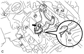
Torque : 12 Nm (123 kgf-cm, 9 ft-lbf)
3. INSTALL CLUTCH RELEASE WITH BEARING CYLINDER ASSEMBLY Installation
4. REMOVE CLUTCH RELEASE BLEEDER SUB-ASSEMBLY Installation
5. INSPECT CLUTCH PIPE LINE Installation
6. INSTALL CLUTCH RELEASE BLEEDER SUB-ASSEMBLY Installation
7. INSTALL CLUTCH FLEXIBLE HOSE BRACKET
(a) Install the clutch flexible hose bracket with the bolt.
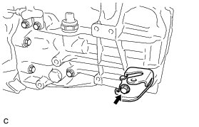
Torque : 12 Nm (120 kgf-cm, 9 ft-lbf)
(b) Install the clutch line to the clutch flexible hose bracket with the bolt.
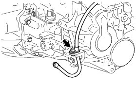
Torque : 19 Nm (192 kgf-cm, 14 ft-lbf)
8. INSTALL CLUTCH ACCUMULATOR ASSEMBLY Installation
9. CONNECT CLUTCH LINE Installation
10. TEMPORARILY INSTALL ENGINE MOUNTING INSULATOR LH Installation
11. INSTALL FRONT ENGINE MOUNTING BRACKET
(a) Install the front engine mounting bracket with the 3 bolts.
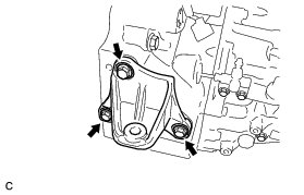
Torque : 64 Nm (653 kgf-cm, 47 ft-lbf)
12. INSTALL MANUAL TRANSAXLE ASSEMBLY
(a) Make sure that the knock pins are not loose, bent, damaged or scratched and then install the transaxle onto the engine with the contact surfaces of the engine and transaxle flat against each other.
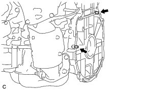
(b) Align the input shaft with the clutch disc and install the manual transaxle onto the engine.
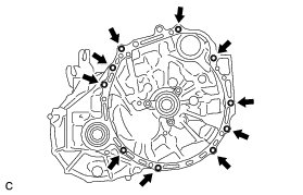
(c) Temporarily tighten the manual transaxle with the 10 bolts.
NOTICE:
* Insert the dowel pins into the dowel holes securely so that the end face of the transaxle assembly fits close against the engine assembly before tightening the bolts.
* Make sure that the dowel pins are not loose, bent, damaged or scratched and then install the transaxle onto the engine with the contact surfaces of the engine and transaxle flat against each other.
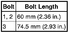
(d) Fully tighten the 3 bolts in the sequence shown in the illustration.
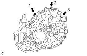
Torque : 64 Nm (653 kgf-cm, 47 ft-lbf)
HINT
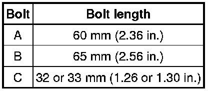
(e) Fully tighten the 7 bolts.
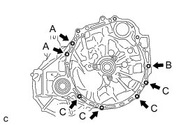
Bolt A, B - Torque : 46 Nm (469 kgf-cm, 34 ft-lbf)
Bolt C - Torque : 44 Nm (449 kgf-cm, 32 ft-lbf)
HINT
13. INSTALL NO. 1 EXHAUST PIPE SUPPORT BRACKET Installation
14. TEMPORARILY INSTALL FRONT ENGINE MOUNTING INSULATOR ASSEMBLY Installation
15. INSTALL FRONT FRAME ASSEMBLY Installation
16. INSTALL FRONT DRIVE SHAFT LH HOLE SNAP RING Reassembly
17. INSTALL FRONT DRIVE SHAFT ASSEMBLY LH Installation
18. INSTALL FRONT DRIVE SHAFT ASSEMBLY RH Installation
19. INSTALL STARTER ASSEMBLY Installation
20. CONNECT WIRE HARNESS
(a) Connect the 2 connectors and install the 2 cables with the 2 bolts.
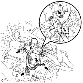
Torque : 12 Nm (123 kgf-cm, 9 ft-lbf)
(b) Install the wire harness to the manual transaxle with the clamp and nut.
Torque : 8.4 Nm (85 kgf-cm, 74 in-lbf)
21. INSTALL ENGINE ASSEMBLY WITH TRANSAXLE
HINT
See the steps from "Install Engine Assembly with Transaxle" through "Check ABS Speed Sensor Signal" Installation.