Power Source Circuit
OTHER SYSTEM: CLOCK: Power Source Circuit
- Power Source Circuit
DESCRIPTION
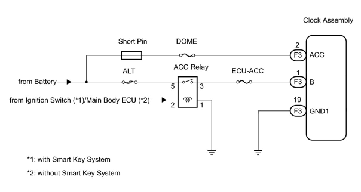
* This circuit is the power source for the clock assembly.
* This circuit provides two types of power sources; one is a constant power source mainly used as a backup power source, and the other is a power source mainly used for signal transmission. The constant power source is mainly used as a backup power source of the clock assembly, however, it is also used for communication.
HINT
If the clock assembly displays "1:00" when the ignition switch turned off, and turned on (IG) again, the B terminal has a malfunction.
WIRING DIAGRAM
INSPECTION PROCEDURE
PROCEDURE
1. INSPECT CLOCK ASSEMBLY
(a) Disconnect the F3 connector.
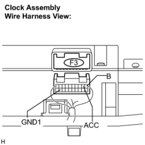
(b) Measure the voltage according to the value(s) in the table below.
Standard voltage:

(c) Measure the resistance according to the value(s) in the table below.
Standard resistance:

NG -- REPAIR OR REPLACE HARNESS OR CONNECTOR
OK -- PROCEED TO NEXT INSPECTION PROCEDURE SHOWN IN PROBLEM SYMPTOMS TABLE