Clock Display Circuit
OTHER SYSTEM: CLOCK: Clock Display Circuit
- Clock Display Circuit
DESCRIPTION
The clock assembly uses this circuit to communicate with the main body ECU via the direct line. The main body ECU uses this circuit to send an auto dimmer signal to the clock assembly. The main body ECU detects the position of the light control switch according to the resistance. When the light control switch is set to the HEAD/TAIL position, the resistance between the HEAD/TAIL terminal and body ground is below 1 Ohms. When the light control switch is set to the HEAD/TAIL position, the main body ECU sends an auto dimmer signal to the clock assembly. When the clock assembly receives an auto dimmer signal from the main body ECU, the clock assembly causes the clock display to be dimmed.
HINT
* The maximum clock assembly margin of error is -4 to 4 seconds per day when the temperature is between -20 (-4°F) and 60°C (140°F).
* If the clock assembly error is greater than specified above, replace the clock assembly.
WIRING DIAGRAM
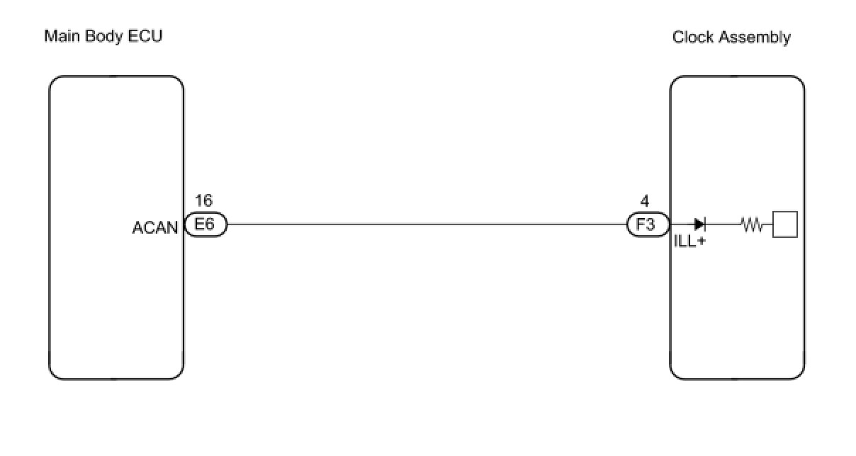
INSPECTION PROCEDURE
PROCEDURE
1. CHECK HARNESS AND CONNECTOR (CLOCK ASSEMBLY - MAIN BODY ECU)
(a) Disconnect the E6 and F3 connectors.
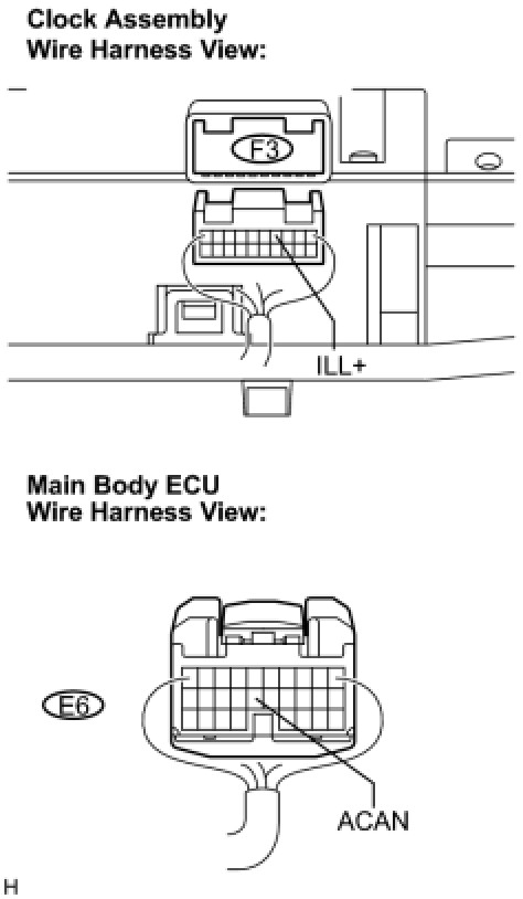
(b) Measure the resistance according to the value(s) in the table below.
Standard resistance:

NG -- REPAIR OR REPLACE HARNESS OR CONNECTOR
OK -- Continue to next step.
2. INSPECT MAIN BODY ECU
(a) Reconnect the F3 connector.
(b) Measure the voltage according to the value(s) in the table below.
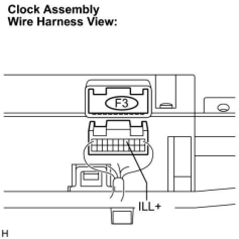
Standard voltage:

NG -- GO TO LIGHTING SYSTEM
OK -- PROCEED TO NEXT INSPECTION PROCEDURE SHOWN IN PROBLEM SYMPTOMS TABLE