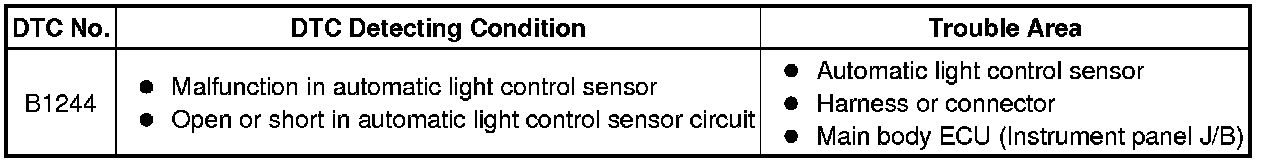
B1244
LIGHTING: LIGHTING SYSTEM: B1244: Light Sensor Circuit Malfunction
B1244 - Light Sensor Circuit Malfunction
DESCRIPTION
The automatic light control sensor detects ambient light, converts it into an electrical signal, and outputs it to the main body ECU. The main body ECU turns on or off the headlights and taillights according to the signal.
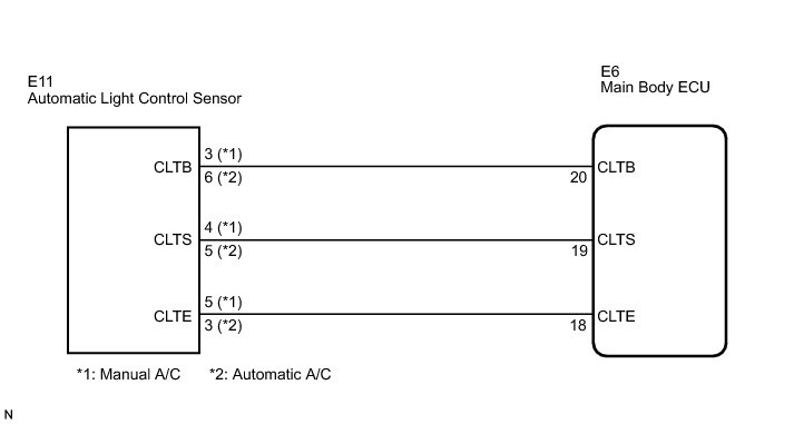
WIRING DIAGRAM
INSPECTION PROCEDURE
PROCEDURE
1. READ VALUE USING TECHSTREAM
(a) Connect Techstream to the DLC3.
(b) Turn the ignition switch on (IG).
(c) Turn Techstream on.
(d) Select the following menu items: Body Electrical / Main Body / Data List.
(e) Read the display on Techstream.
Main Body:

OK:
Normal condition listed above is displayed.
OK -- REPLACE INSTRUMENT PANEL JUNCTION BLOCK ASSEMBLY
NG -- Continue to next step.
2. CHECK VEHICLE CONDITION
Result:
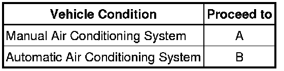
B -- CHECK HARNESS AND CONNECTOR (MAIN BODY ECU - AUTOMATIC LIGHT CONTROL SENSOR)
A -- Continue to next step.
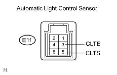
3. CHECK HARNESS AND CONNECTOR (MAIN BODY ECU - AUTOMATIC LIGHT CONTROL SENSOR)
(a) Disconnect the E11 automatic light control sensor connector.
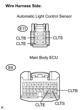
(b) Disconnect the E6 main body ECU connector.
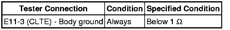
(c) Measure the resistance according to the value(s) in the table below.
Standard resistance:
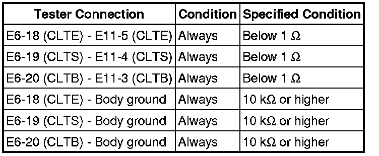
NG -- REPAIR OR REPLACE HARNESS OR CONNECTOR
OK -- Continue to next step.
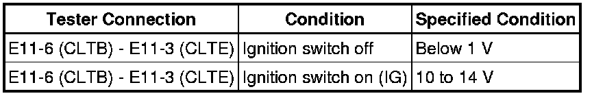
4. INSPECT MAIN BODY ECU (INSTRUMENT PANEL JUNCTION BLOCK ASSEMBLY)
(a) Reconnect the main body ECU connector.
(b) Measure the voltage and resistance according to the value(s) in the table below.
Standard voltage:
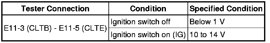
Standard resistance:

NG -- REPLACE INSTRUMENT PANEL JUNCTION BLOCK ASSEMBLY
OK -- Continue to next step.
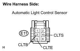
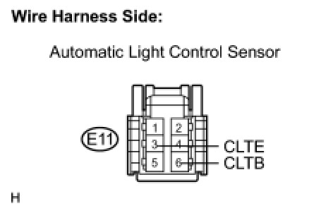
5. INSPECT AUTOMATIC LIGHT CONTROL SENSOR
(a) Reconnect the automatic light control sensor connector.
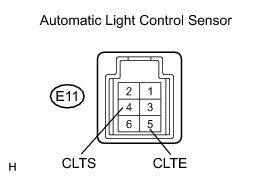
(b) Connect an oscilloscope to the automatic light control sensor connector.
(c) Check the waveform.
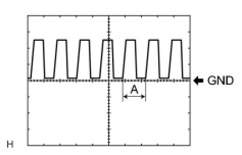
OK:

HINT
If the ambient light becomes brighter, width A becomes narrower.
NG -- REPLACE AUTOMATIC LIGHT CONTROL SENSOR
OK -- REPLACE INSTRUMENT PANEL JUNCTION BLOCK ASSEMBLY
6. CHECK HARNESS AND CONNECTOR (MAIN BODY ECU - AUTOMATIC LIGHT CONTROL SENSOR)
(a) Disconnect the E11 automatic light control sensor connector.
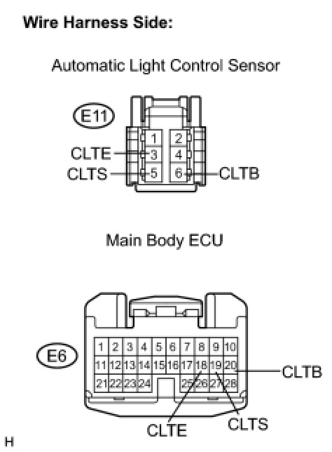
(b) Disconnect the E6 main body ECU connector.
(c) Measure the resistance according to the value(s) in the table below.
Standard resistance:

NG -- REPAIR OR REPLACE HARNESS OR CONNECTOR
OK -- Continue to next step.
7. INSPECT MAIN BODY ECU (INSTRUMENT PANEL JUNCTION BLOCK ASSEMBLY )
(a) Reconnect the main body ECU connector.
(b) Measure the voltage and resistance according to the value(s) in the table below.
Standard voltage:
Standard resistance:
NG -- REPLACE INSTRUMENT PANEL JUNCTION BLOCK ASSEMBLY
OK -- Continue to next step.
8. INSPECT AUTOMATIC LIGHT CONTROL SENSOR
(a) Reconnect the automatic light control sensor connector.
(b) Connect an oscilloscope to the automatic light control sensor connector.
(c) Check the waveform.
OK:

HINT
If the ambient light becomes brighter, width A becomes narrower.
NG -- REPLACE AUTOMATIC LIGHT CONTROL SENSOR
OK -- REPLACE INSTRUMENT PANEL JUNCTION BLOCK ASSEMBLY