Pinout Values and Diagnostic Parameters
LIGHTING: LIGHTING SYSTEM: TERMINALS OF ECU
1. CHECK MAIN BODY ECU (INSTRUMENT PANEL J/B)
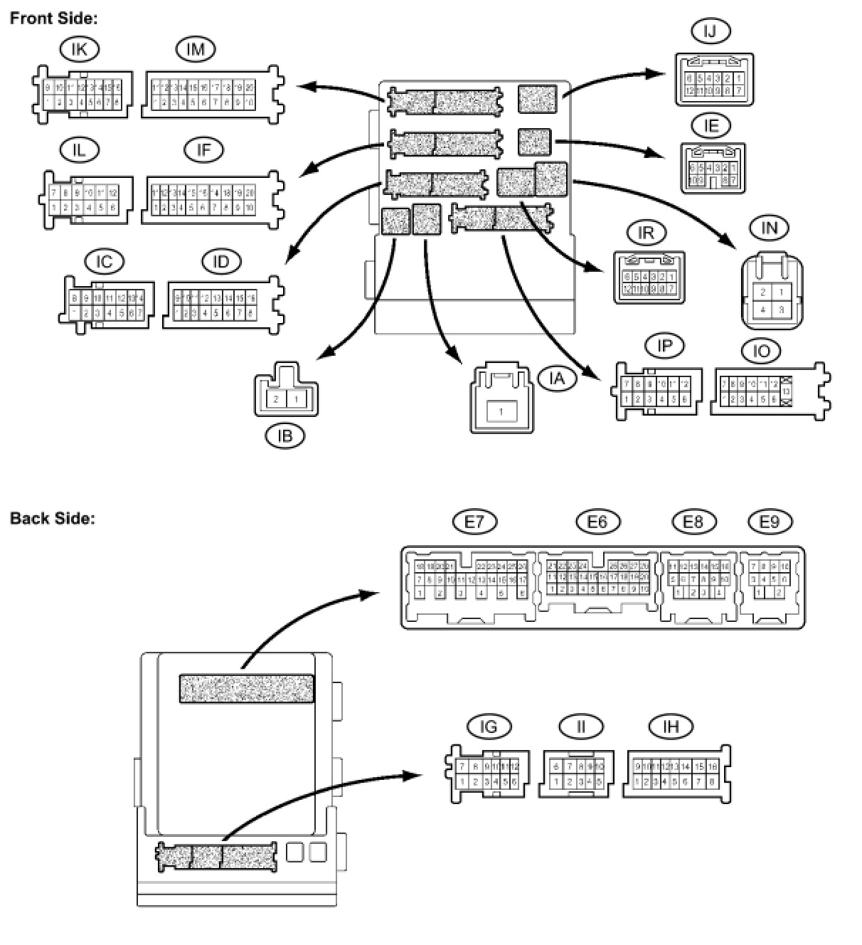
(a) Disconnect the IA, ID, IF and IM J/B connectors.
(b) Measure the voltage and resistance between the specified terminals of the wire harness side connectors and body ground.
Standard voltage:

Standard resistance:

If the result is not as specified, there may be a malfunction on the wire harness side.
(c) Reconnect the IA, ID, IF, and IM J/B connectors.
(d) Measure the resistance and voltage between the specified terminals of the J/B connectors and body ground.
Standard resistance:

Standard voltage:
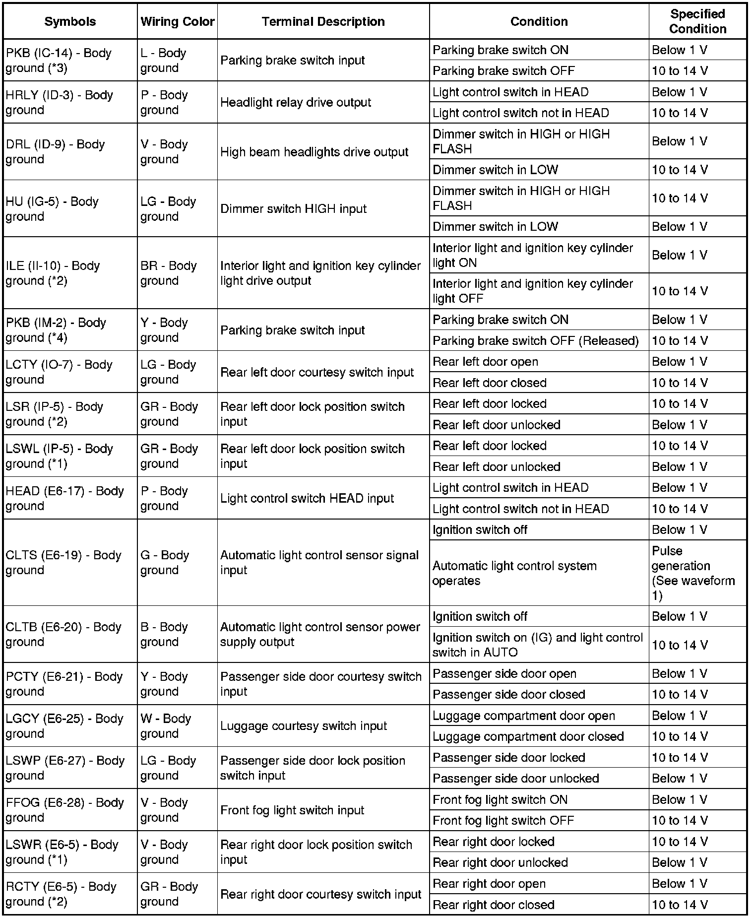
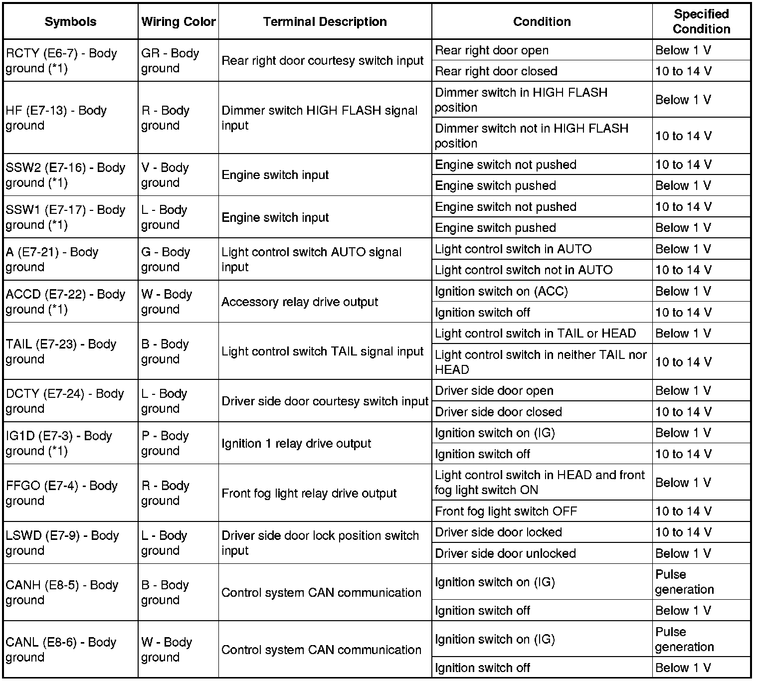
If the result is not as specified, the main body ECU (Instrument panel J/B) may have a malfunction.
HINT
*1: with smart key system
*2: without smart key system
*3: Pedal type parking brake
*4: Lever type parking brake
(1) Waveform 1
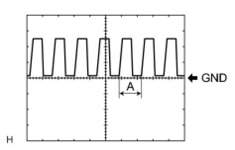
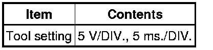
HINT
If the ambient light becomes brighter, width A becomes narrower.