Light Control Switch Circuit
LIGHTING: LIGHTING SYSTEM: Light Control Switch Circuit
- Light Control Switch Circuit
DESCRIPTION
This circuit detects the condition of the headlight dimmer switch assembly.
WIRING DIAGRAM
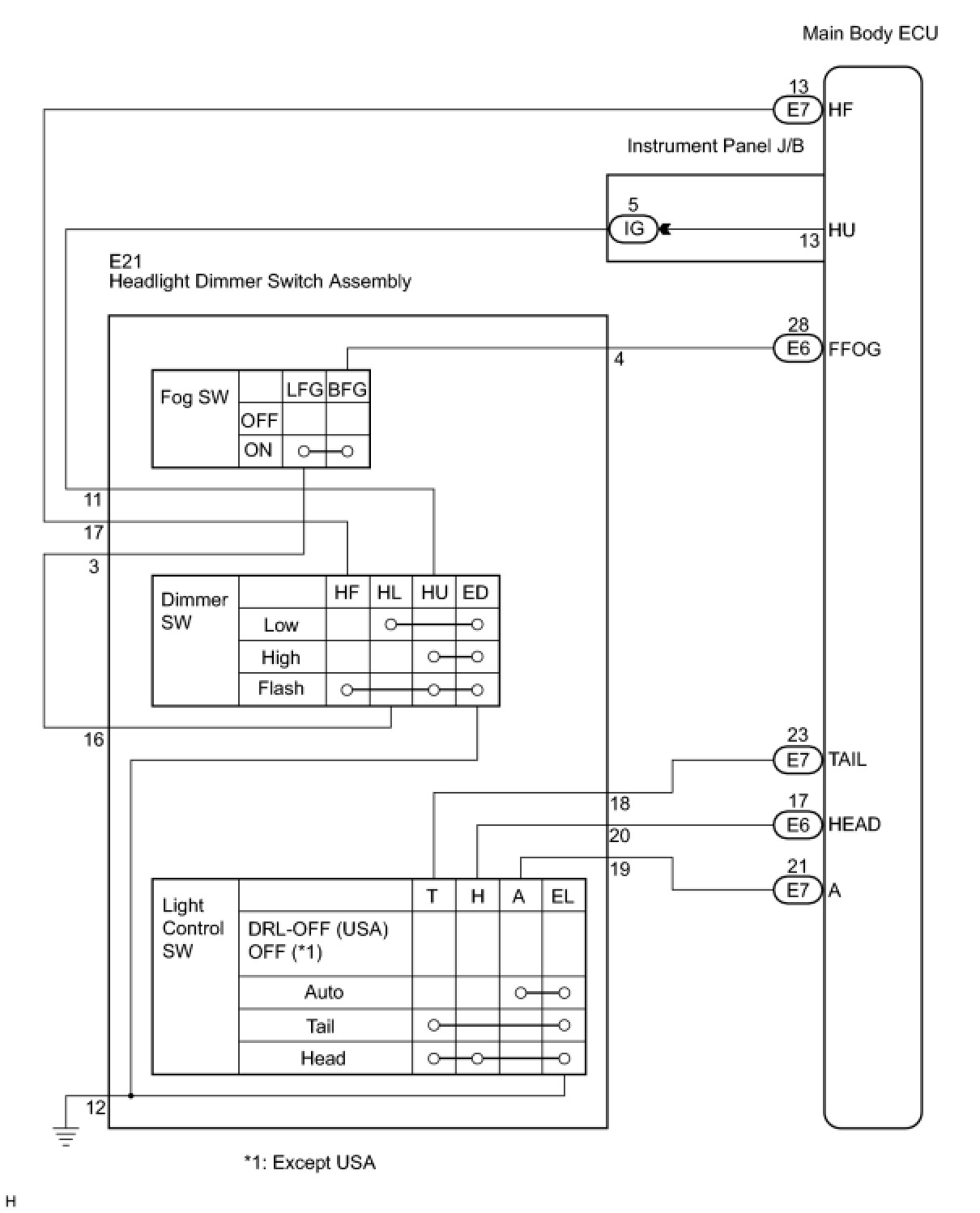
INSPECTION PROCEDURE
PROCEDURE
1. READ VALUE USING TECHSTREAM
(a) Connect Techstream to the DLC3.
(b) Turn the ignition switch on (IG).
(c) Turn Techstream on.
(d) Select the following menu items: Body Electrical / Main Body / Data List.
(e) Read the display on Techstream.
Main Body:
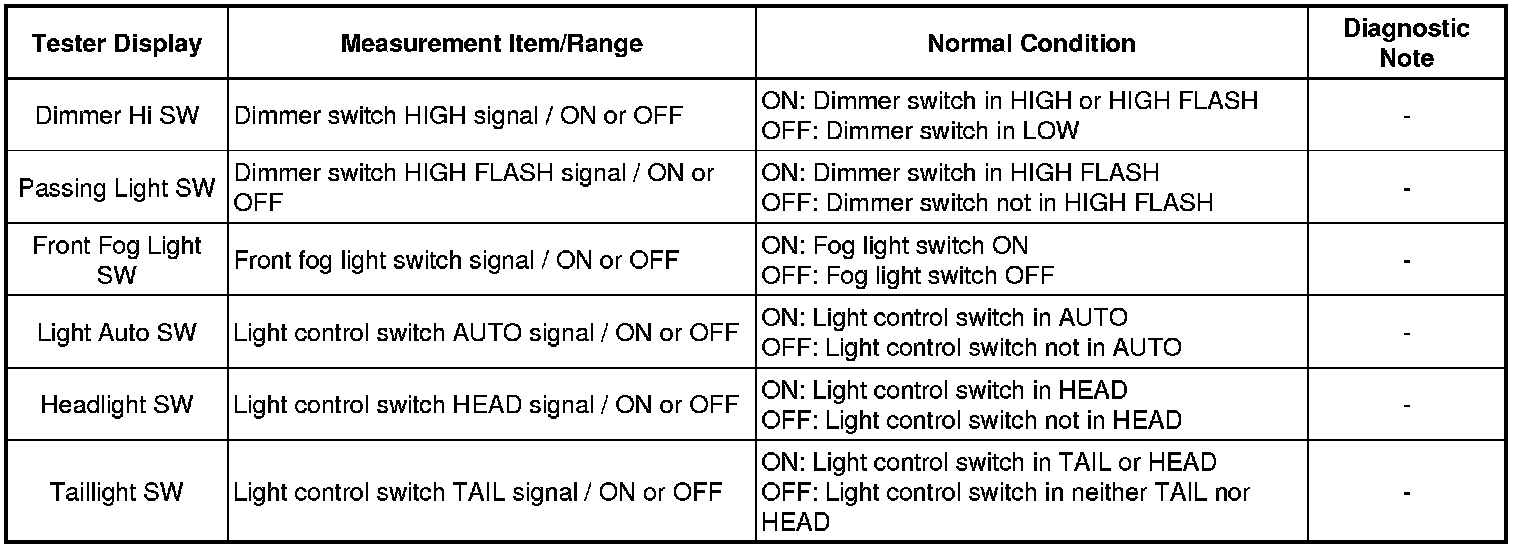
OK:
Normal conditions listed above are displayed.
OK -- PROCEED TO NEXT CIRCUIT INSPECTION SHOWN IN PROBLEM SYMPTOMS TABLE
NG -- Continue to next step.
2. INSPECT HEADLIGHT DIMMER SWITCH ASSEMBLY
(a) Inspect the headlight dimmer switch assembly Testing and Inspection.
OK:
Headlight dimmer switch assembly is normal.
NG -- REPLACE HEADLIGHT DIMMER SWITCH ASSEMBLY
OK -- Continue to next step.
3. CHECK HARNESS AND CONNECTOR (INSTRUMENT PANEL J/B ASSEMBLY - SWITCH ASSEMBLY)
(a) Disconnect the E21 headlight dimmer switch assembly connector.
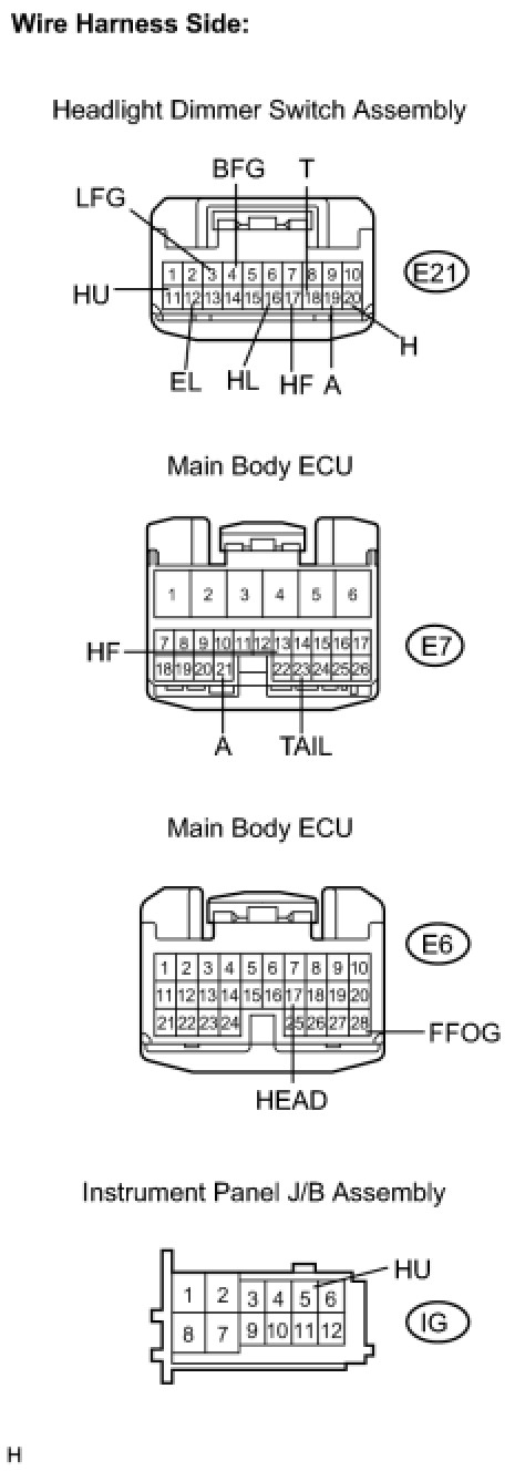
(b) Disconnect the E6 and E7 main body ECU connectors.
(c) Disconnect the IG instrument panel J/B connector.
(d) Measure the resistance according to the value(s) in the table below.
Standard resistance:
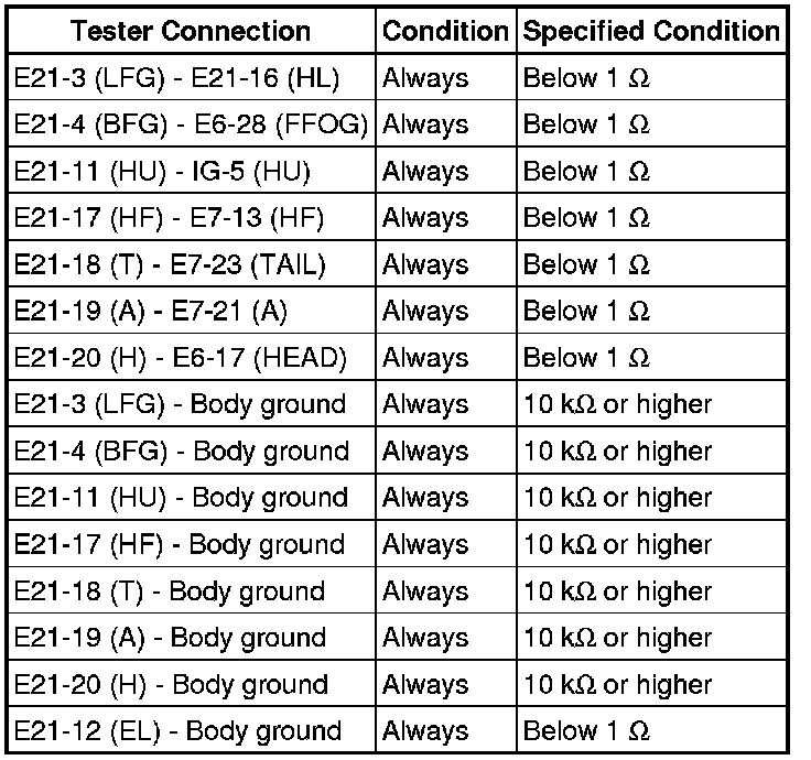
NG -- REPAIR OR REPLACE HARNESS OR CONNECTOR
OK -- REPLACE INSTRUMENT PANEL JUNCTION BLOCK ASSEMBLY