Meter / Gauge System
METER: METER / GAUGE SYSTEM: SYSTEM DIAGRAM
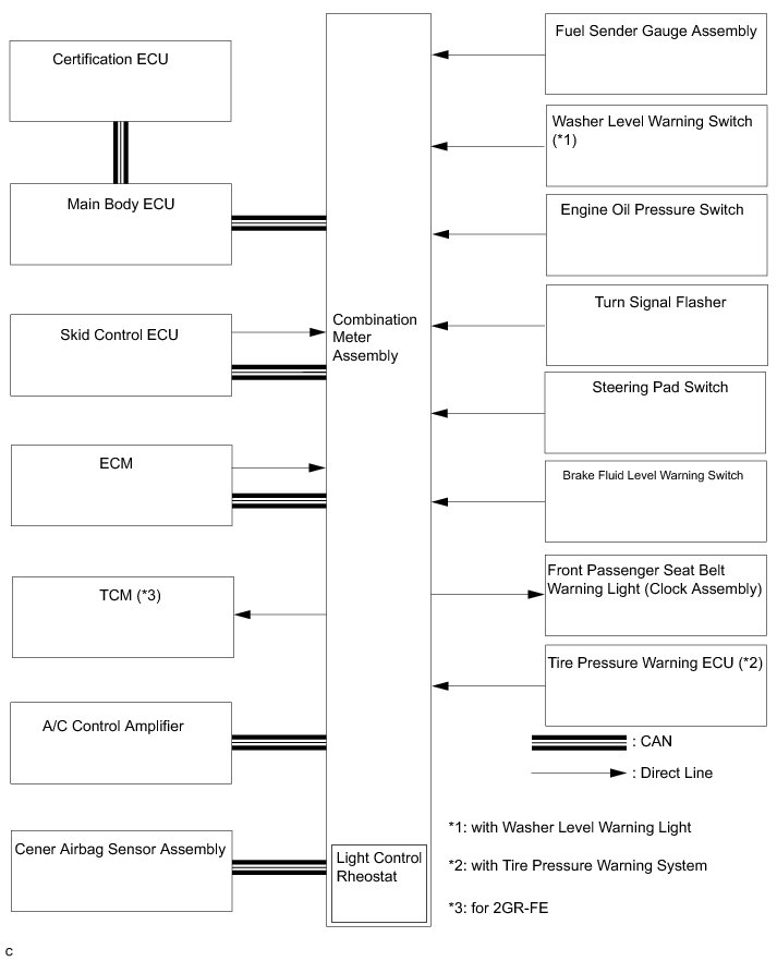
INPUT AND OUTPUT SIGNALS OF THE COMBINATION METER ASSEMBLY:
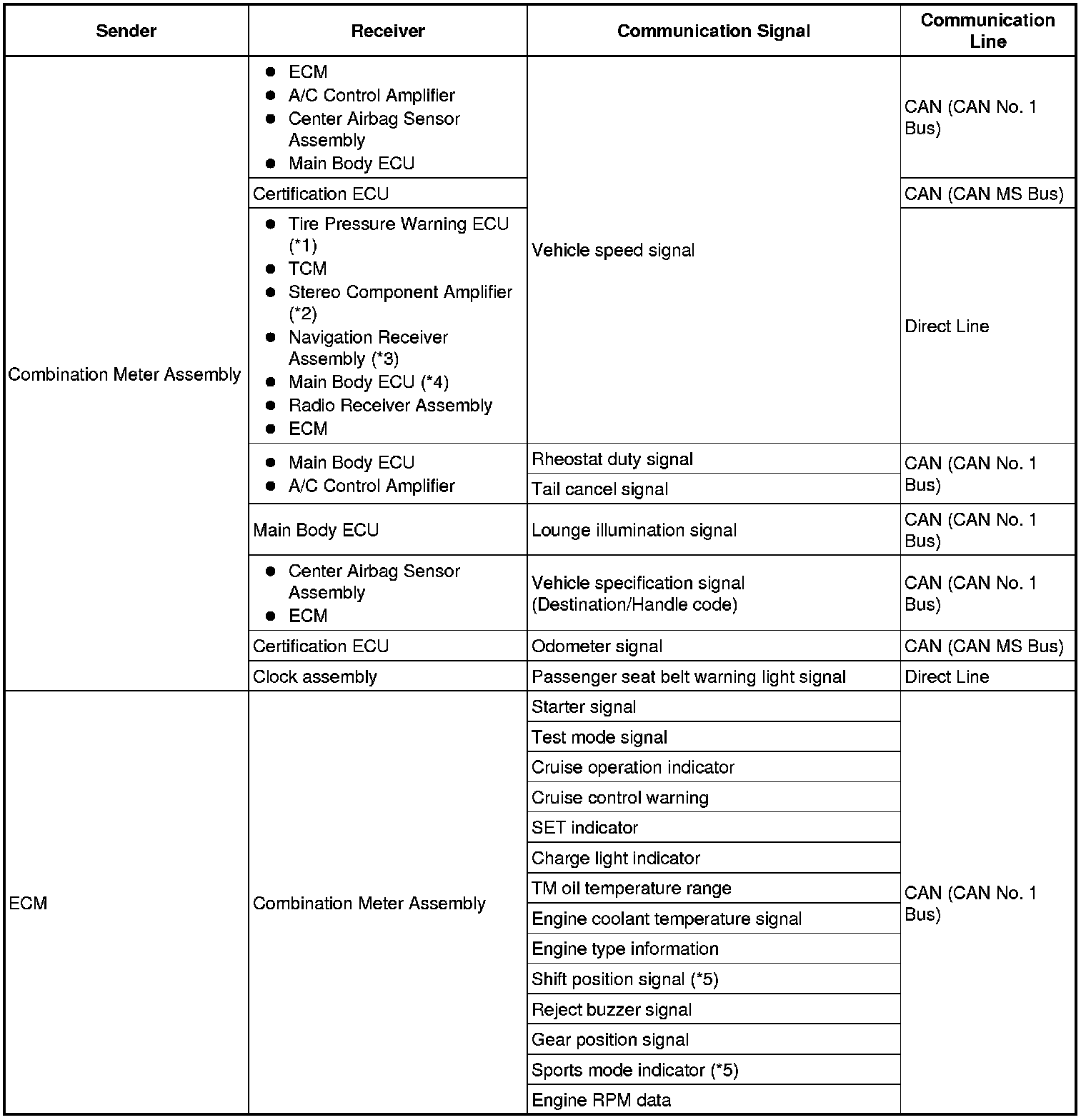
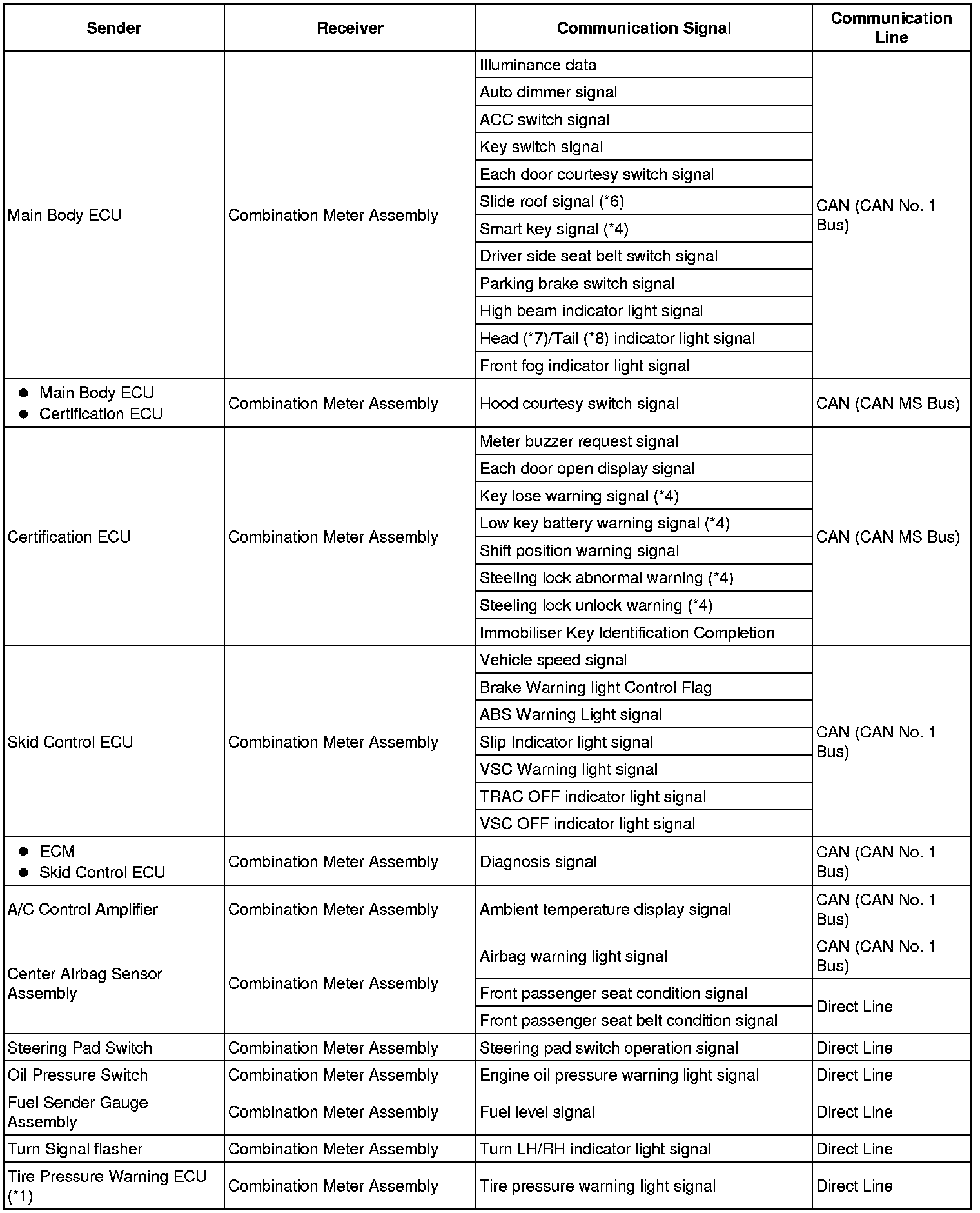

*1: with Tire Pressure Warning System
*2: for Separate Type Amplifier System
*3: with Navigation System
*4: with Smart Key System
*5: for Automatic Transaxle
*6: with Sliding Roof
*7: for U.S.A.
*8: for Canada
*9: with Washer Level Warning Light
1. METER GAUGE
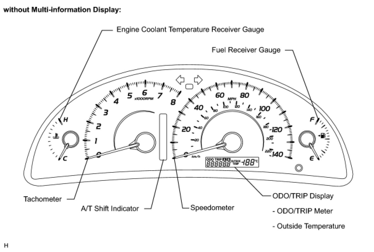
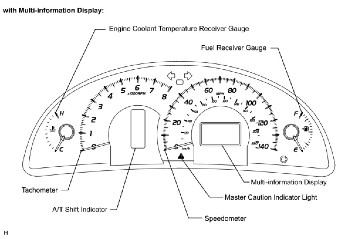
METER GAUGE:
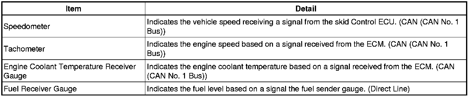
WARNING/INDICATOR:
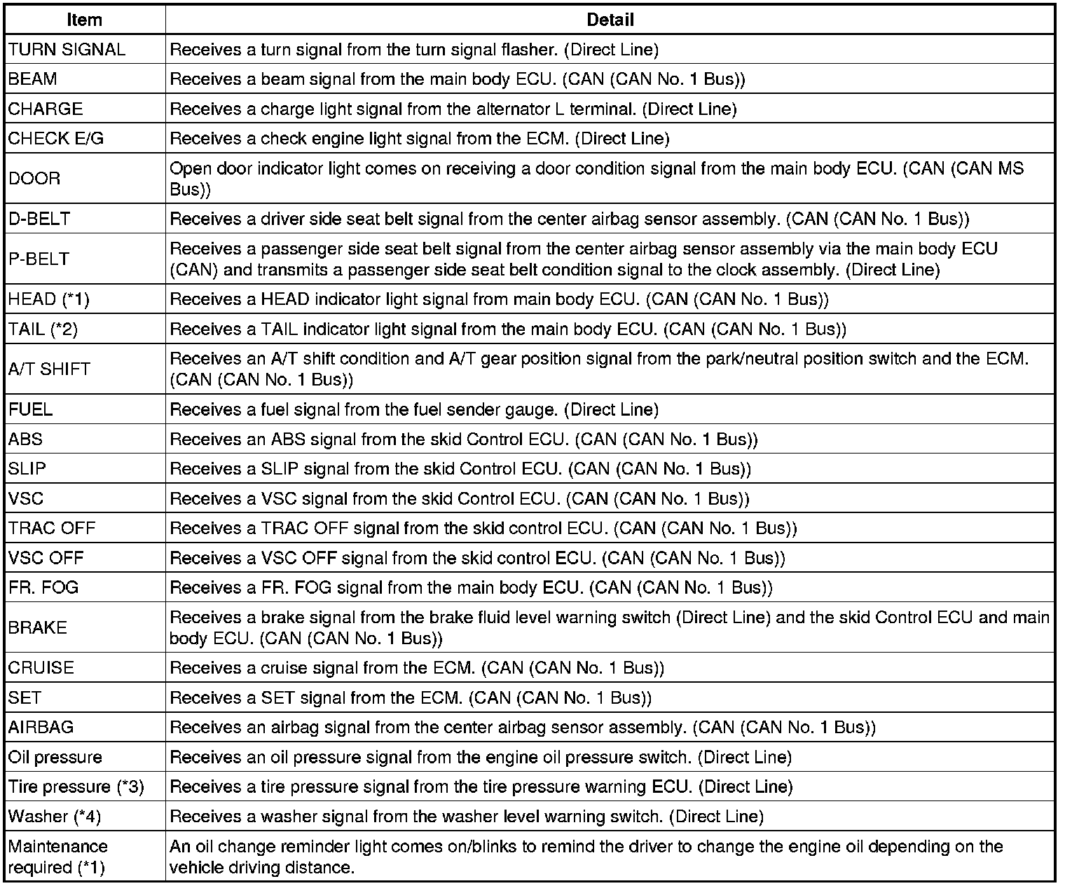
*1: for U.S.A.
*2: except for U.S.A.
*3: with Tire Pressure Warning System
*4: with Washer Level Indicator
HINT
* The multi-information display has been located in the center of the combination meter assembly.
* The display shows a message or animation for each of the functions described in the table below.
MULTI-INFORMATION DISPLAY:
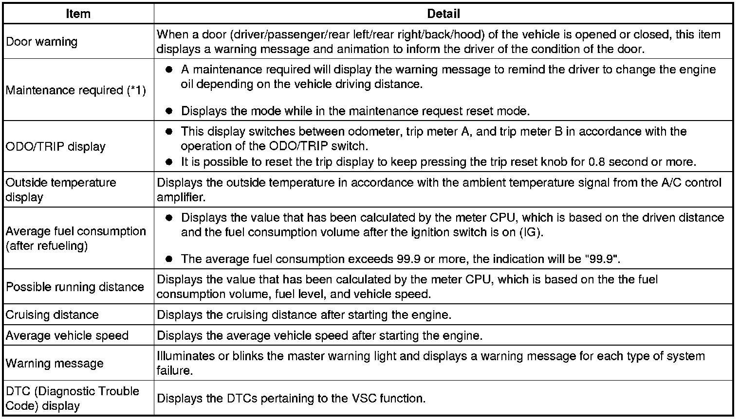
*1: for U.S.A.
*2: Except for U.S.A.
2. MULTI-INFORMATION DISPLAY
HINT
Illustrations may differ from the actual screen displayed depending on the specifications of the vehicle.
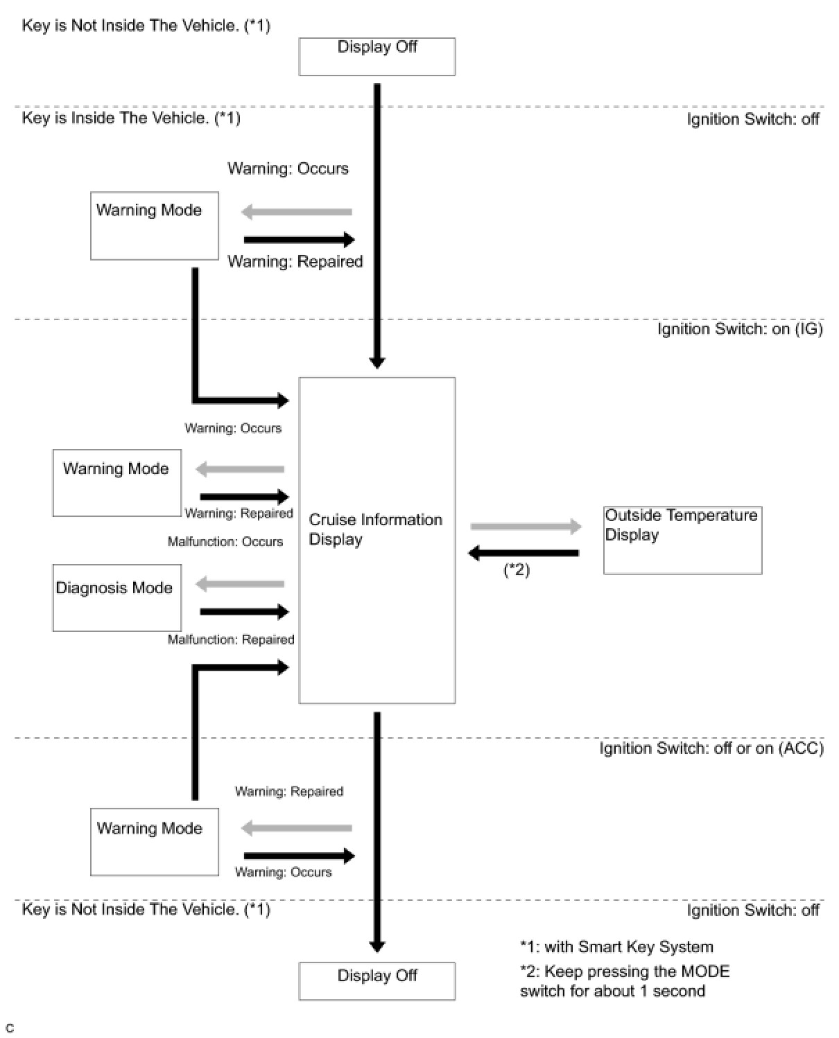
(a) for English
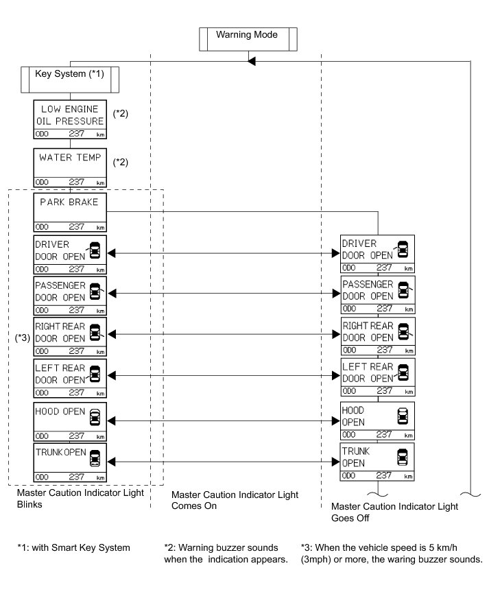
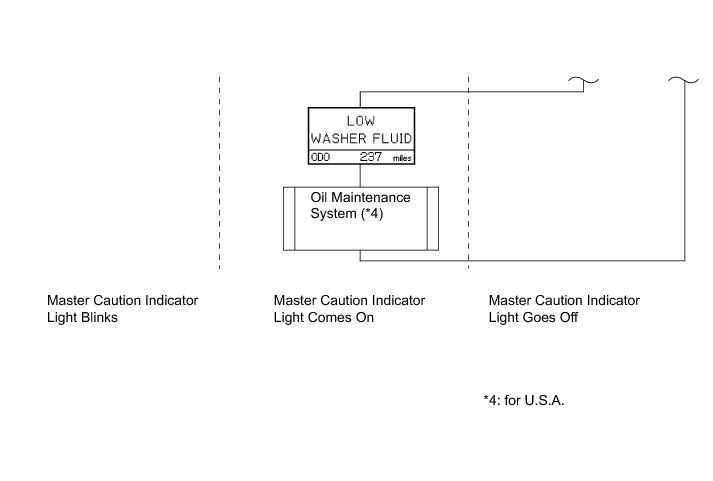
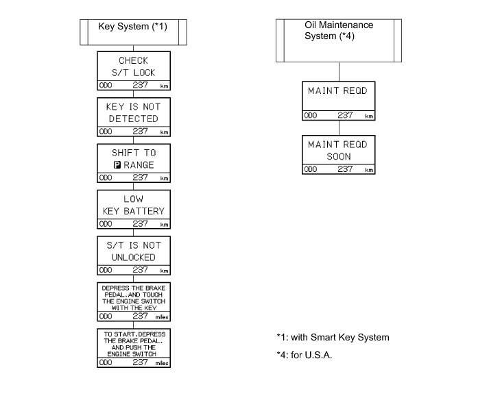
(b) for French
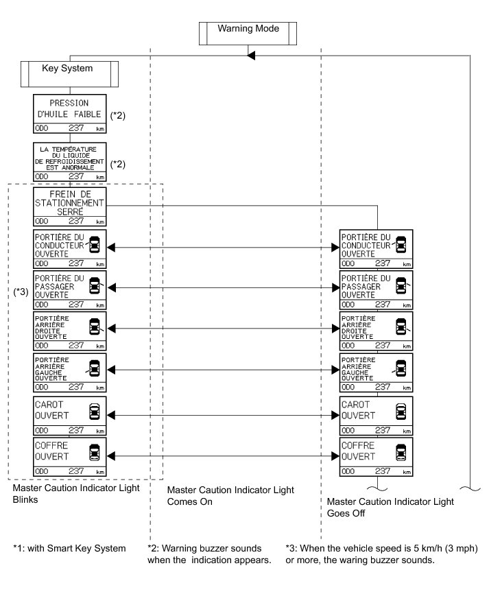
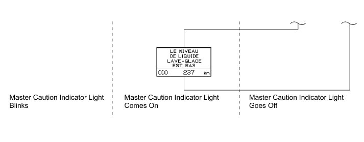
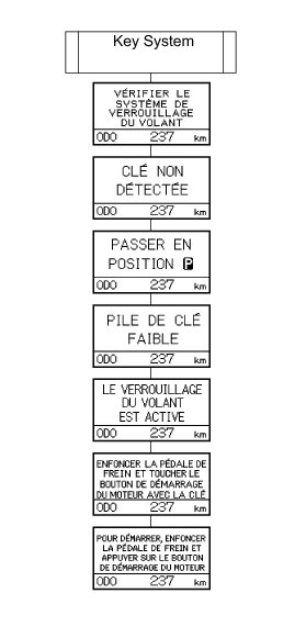
HINT
* The multi-information display shows "DIAG" when turn the ignition switch on (IG) Vehicle Stability Control System (for ADVICS Made) for ADVICS, Vehicle Stability Control System (for BOSCH Made) for BOSCH).
* Diagnosis information can be displayed on the multi-information display after connecting a jumper wire between TC and CG of the DLC3 connector.