Diagnosis Circuit
ENGINE IMMOBILISER: ENGINE IMMOBILISER SYSTEM (w/o Smart Key System): Diagnosis Circuit
- Diagnosis Circuit
DESCRIPTION
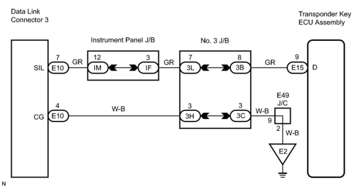
This circuit is used to read the DTCs that are output from the transponder key ECU assembly with Techstream.
WIRING DIAGRAM
INSPECTION PROCEDURE
NOTICE:
If the transponder key ECU assembly is replaced, register the key and ECU communication ID Engine Immobiliser System (W/O Smart Key System).
PROCEDURE
1. CHECK HARNESS AND CONNECTOR (TRANSPONDER KEY ECU - DLC3)
(a) Disconnect the E15 ECU connector.
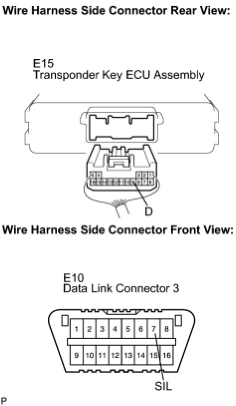
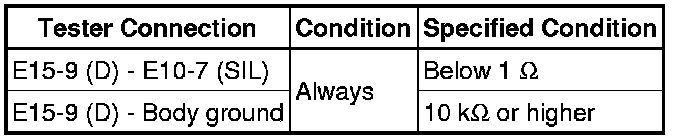
(b) Measure the resistance according to the value(s) in the table below.
Standard resistance:
NG -- REPAIR OR REPLACE HARNESS OR CONNECTOR
OK -- Continue to next step.
2. CHECK HARNESS AND CONNECTOR (DLC3 - BODY GROUND)
(a) Measure the resistance according to the value(s) in the table below.
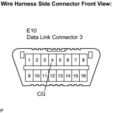
Standard resistance:

NG -- REPAIR OR REPLACE HARNESS OR CONNECTOR
OK -- PROCEED TO NEXT CIRCUIT INSPECTION SHOWN IN PROBLEM SYMPTOMS TABLE